High resolution oscilloscope

SDS1000X HD Series

SDS1000X HD

Bandwidth

200 MHz

Real time sampling rate

2 GSa/s

Channels

4+EXT

SDS1000X HD

SDS1000X HD

Created with Pixso.

Product Introduction

SDS1000X HD series oscilloscopes not only retain their educational and friendly characteristics, but also improve their performance. The bandwidth is extended to100 MHz to 200 MHz to meet a wider range of teaching and experimental needs. The high-resolution display in HD mode makes the waveform more delicate and improves the learning experience.

Key Features

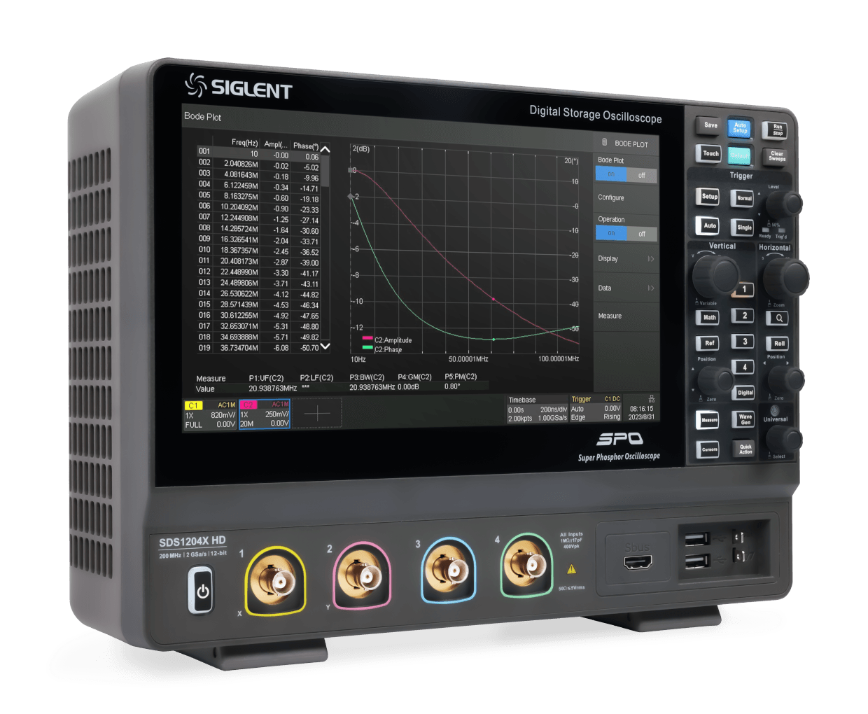
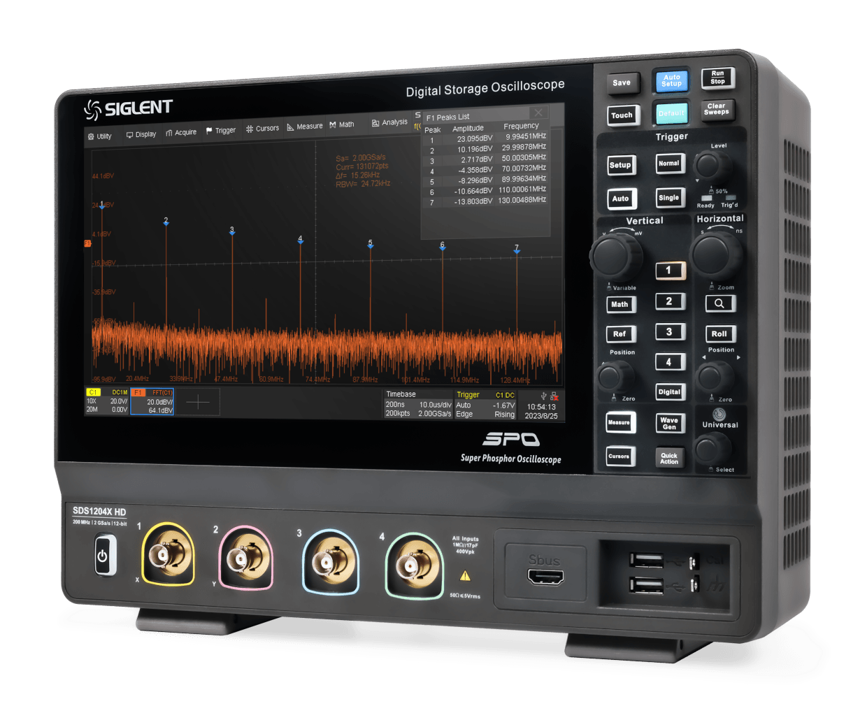
  • Bandwidth:100MHz,200 MHz
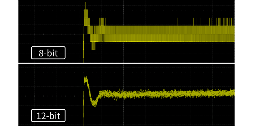
  • ADC:12-bit
  • Real time sampling rate: 2 GSa/s
  • Memory Depth: 100 Mpts/ch(One channel mode)
  • Capture rate:500,000 wfm/s(Sequence Mode)
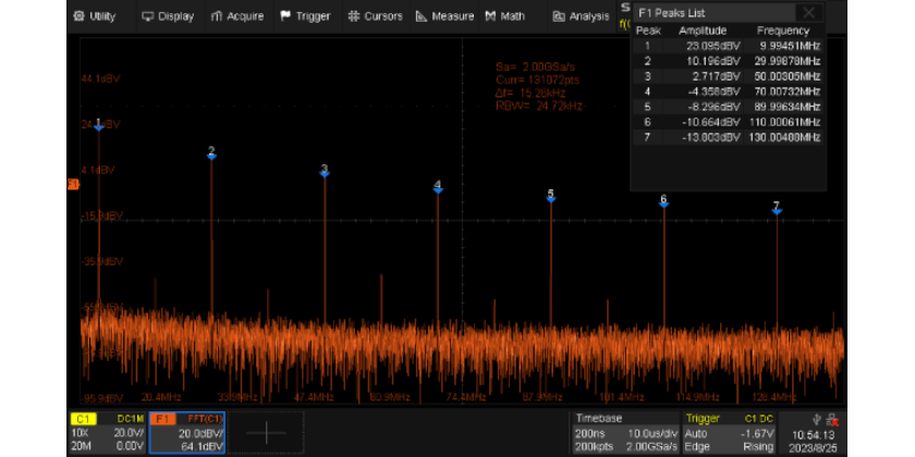
  • Front ends with 70 μVrms noise floor @ 200 MHz bandwidth

Product advantage

12-bit high resolution:
perfectly restore waveform details

SDS1000X HD adopts a 12-bit analog-to-digital converter, which can achieve 4096 quantization levels, which is 16 times the signal resolution of traditional 8-bit oscilloscopes. Combined with the excellent noise floor, it can make the captured waveforms appear more clearly on the screen, which is conducive to the user’s observation as well as accurate measurement.

FFT: perfect combination of
time and frequency domain

With hardware accelerated FFT function, the maximum number of operation points is 2Mpts, which provides superior spectral resolution while still maintaining a high spectral refresh rate. FFT supports multiple window functions, three modes of normal, average and maximum hold, and can automatically mark the peak points and form a list.

Standard 7 kinds of decoding:
suitable for multiple scenarios

SDS1000X HD comes standard with I2C, SPI, UART, CAN, LIN, CAN FD, FlexRay, and the decoding results can be displayed in hexadecimal, decimal, binary, or ASCII format, and two parallel buses can be decoded at the same time, each of which is displayed as a graphic icon on the left side of the screen. In addition, the settings for the signals and the bus configurations can be synchronized to the triggers through the “Copy to trigger” function.

Power Analysis:
beneficial to power supply design

Power Analysis can help users to quickly measure and analyze a variety of items in the power electronics field, such as power quality, harmonics, inrush current, switching loss, etc. Power Analysis can also be used to analyze the power loop response in combination with Bode Plot. When you turn on the power analysis function, you can use the voltage and current probes correctly according to the “Connection Guide”.

16 digital channels: realizing
mixed signal acquisition and analysis

16 Channels Logic Analyzer can add 16 digital channels to the instrument without affecting other test functions, which can quickly solve the problems of analog-digital mixed-signal design and analysis.

Product parameter

Configure your instrument

Add to Compare ModelsBandwidthChannelsVertical ResolutionSampling RateMemory DepthCapture Rate Price  

Resources

Hide Created with Pixso.