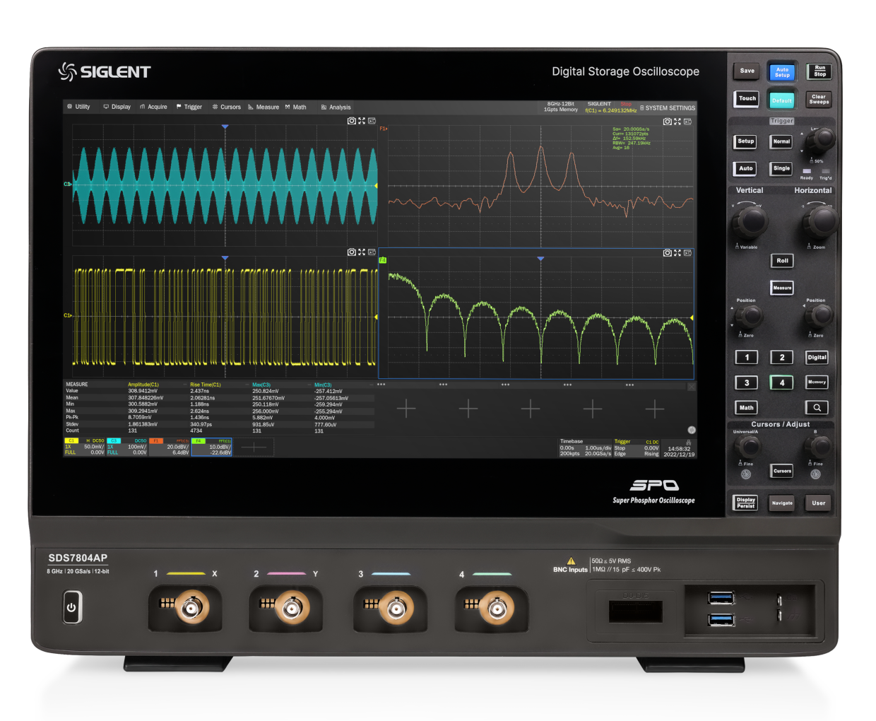
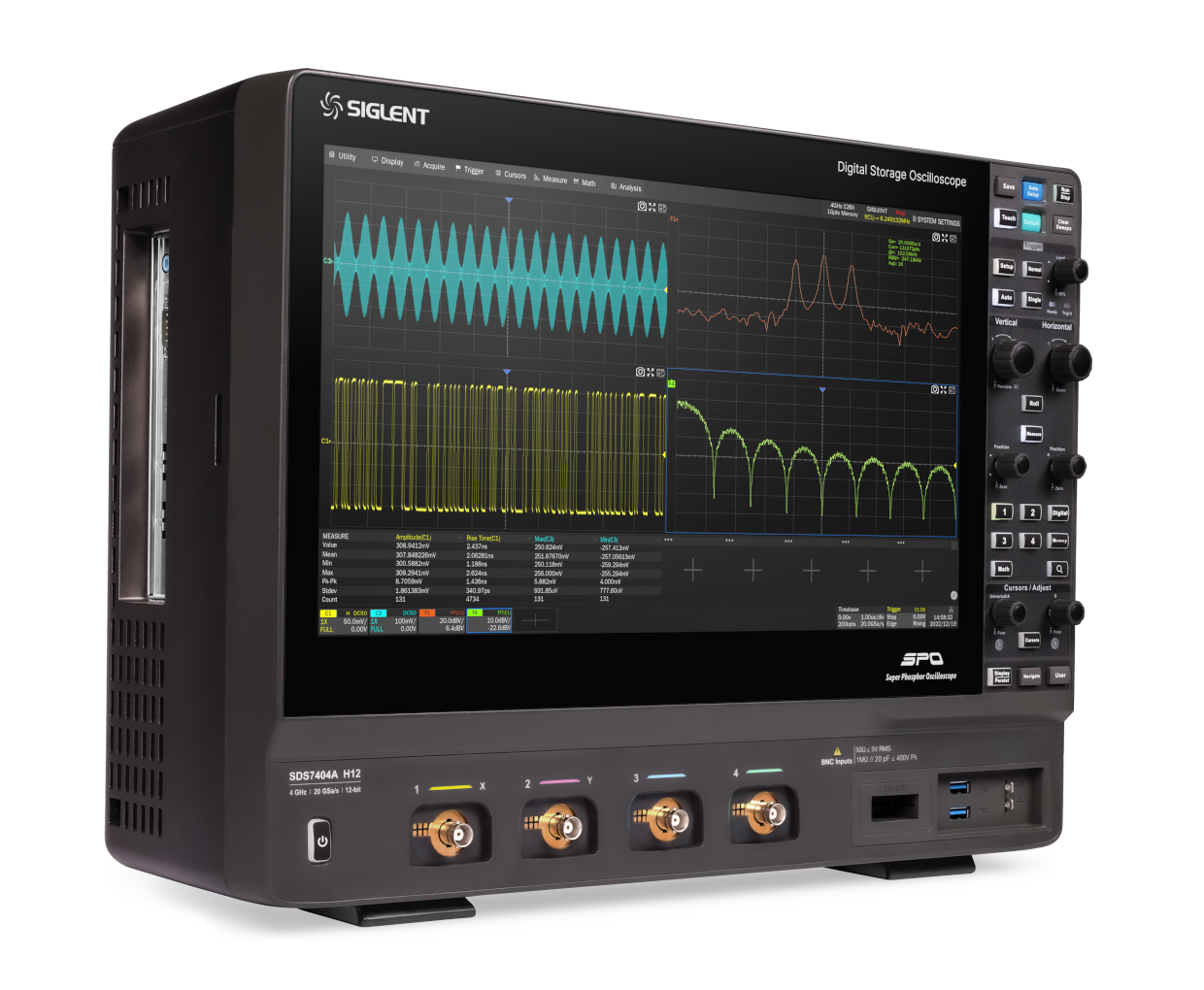
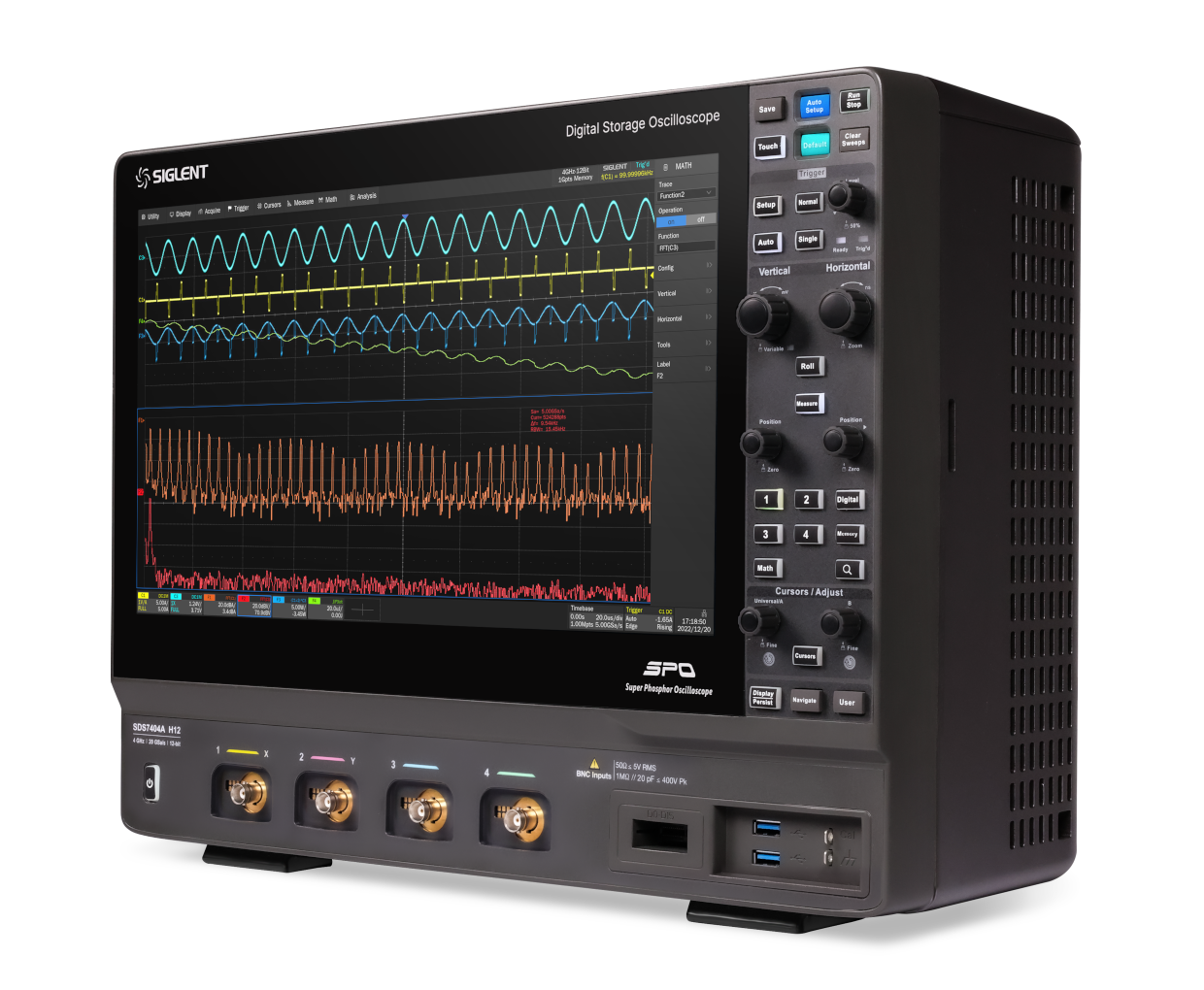
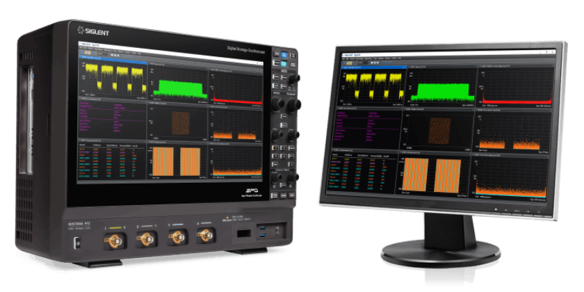
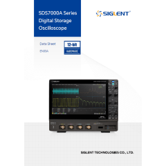
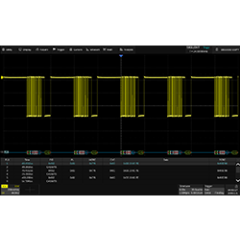
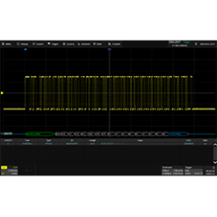
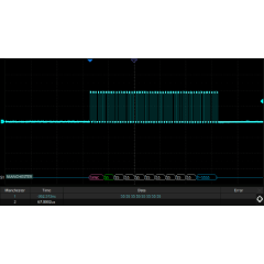
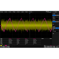
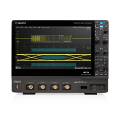
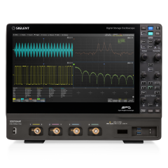
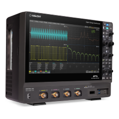
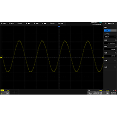
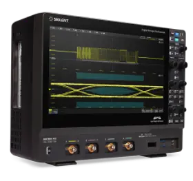
SDS7000A series, as the new flagship oscilloscope products of Siglent Technology, the maximum bandwidth is increased to 6GHz, the rise time is only 58ps, which is more than twice as fast as the oscilloscope with 4GHz bandwidth, and it can support the measurement of signals such as MIPI-DPHY, DDR2/DDR3, USB2.0, SATA1, DDR1/2/3 and so on, which makes the application scenarios more diversified; and it also adopts the Meanwhile, it adopts a new 15.6-inch high-definition touch screen and supports split-screen display function, which brings a brand-new measurement experience.
Key Features
Bandwidth: 8 GHz, 6 GHz, 4 GHz, 3 GHz Memory depth: up to 2 Gpts/ channel ADC: 12-bit Real-time sampling rate: up to 20 GSa/s Waveform capture rate: up to 1,000,000 wfm/s
Product advantage
Restore the signal perfectly
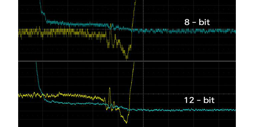
The sampling rate of 20 GSa/s eliminates signal distortion. With a long storage depth of up to 1 Gpts/ch, capture complete signal sequences for up to 50 millisec at max sampling rate without any gaps. Utilize search and navigate or history tools to analyze the entire stored trace. Each sample utilizes the 12-bit ADC, limiting the quantization error, which can help engineers to observe the details of the waveform clearly and measure the waveform accurately.
Real-Time Spectrum Analysis (RTSA)
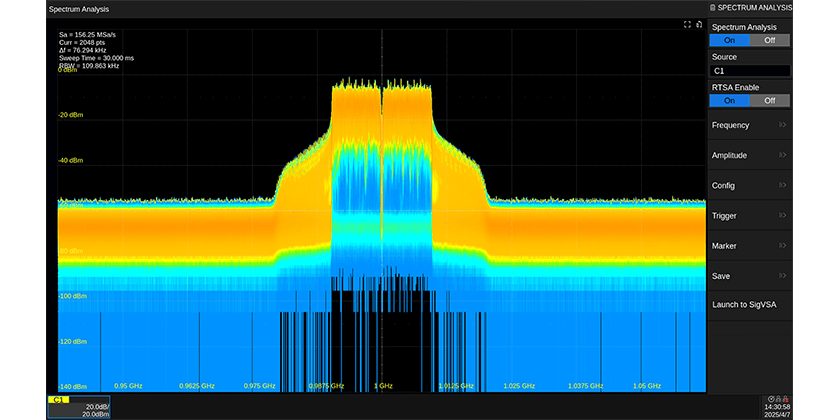
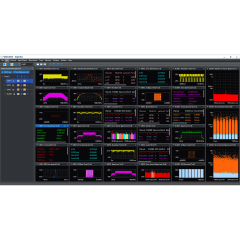
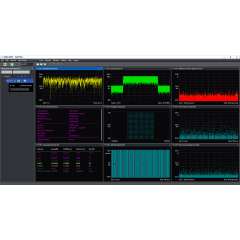
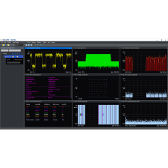
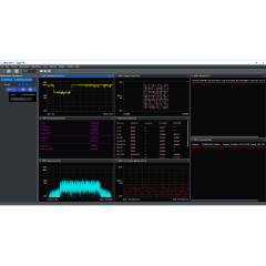
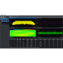
Equipped with RTSA and digital down-conversion (DDC) technologies, the SDS7000A supports up to 1 GHz Real-Time analysis bandwidth. Advanced display modes include density plots, spectrum monitoring, and 3D visualizations. Compared to traditional superheterodyne spectrum analyzers, the SDS7000A offers higher bandwidth and faster signal acquisition — ideal for capturing transient events in 5G NR, 4G LTE, and Wi-Fi.
Vector Signal Analysis (SigVSA)
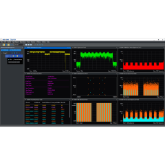
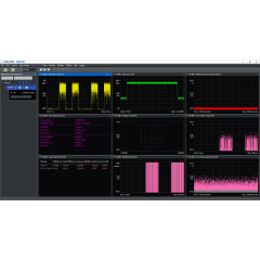
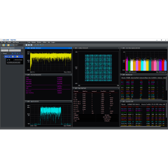
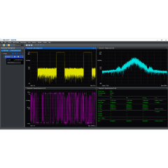
SDS7000A integrates vector signal analysis software SigVSA on the device. With the help of the built-in SigVSA, the oscilloscope can directly analyze the signal of DDC output data. The supported signal types range from simple BPSK to complex broadband signals, such as 4LTE, 5NR, IEEE802.11b/a/g/n/ac/ax/be and 4096QAM. In addition, the user can directly obtain the real-time waveform from the oscilloscope for analysis, and can also analyze the saved waveform data file off-line.
Eye/Jitter analysis
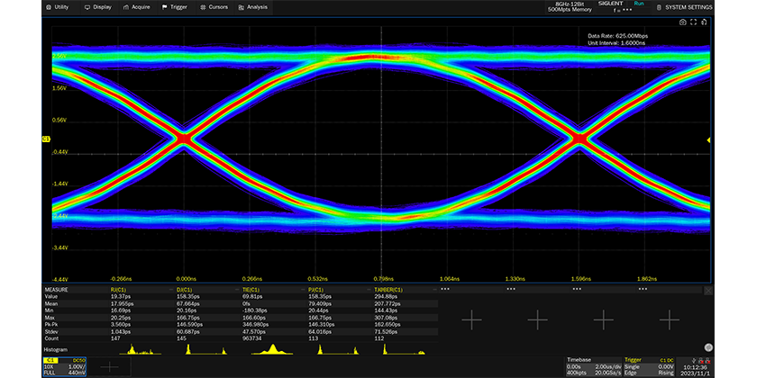
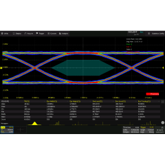
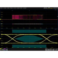
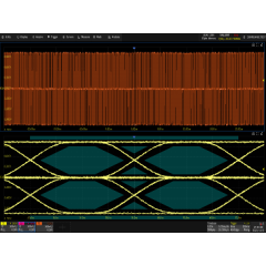
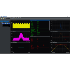
As the core of signal integrity analysis of high-speed systems, eye diagrams characterize high speed communication signals. The quality of the system can be evaluated by observing the influence of inter-symbol crosstalk, noise, and bandwidth. Jitter analysis characterizes the statistical distribution of small timing changes in a systems and is often used to debug digital communication systems and high-speed signal transmission. The SDS7000A series supports automatic parameter measurements for jitter and eye characterization. Easy setup and automatic measurements speed debugging and simplify engineering design testing.
Protocol consistency analysis
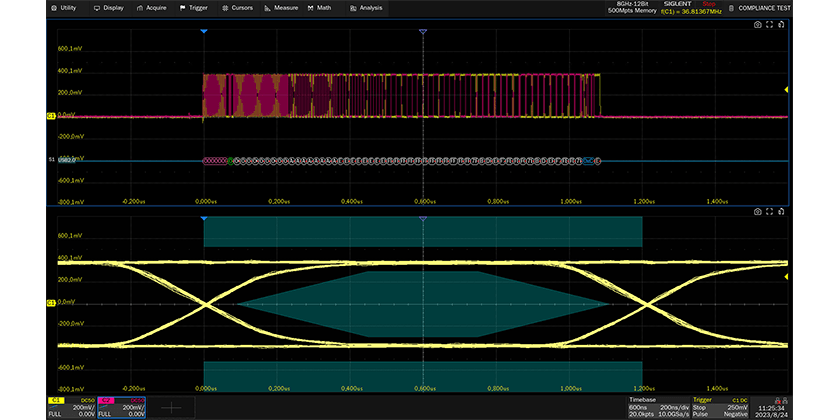
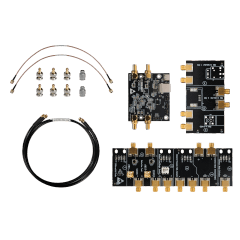
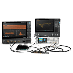
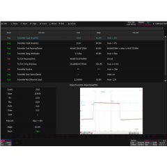
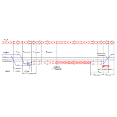
USB 2.0, 100Base-TX, 1000Base-T, 2.5G/5G/10GBase-T, 100Base-T1, 1000Base-T1, MIPI-DPHY protocol conformance testing are available. When the user sets up the environment according to the prompts, by using the related test fixture, the oscilloscope and related instruments can be automatically set up and related measurement, calculation, decoding and other functions will be used for testing, helping the user to complete each test project quickly and efficiently, and reports are generated automatically.
SAP5000D active differential probe(5GHz)
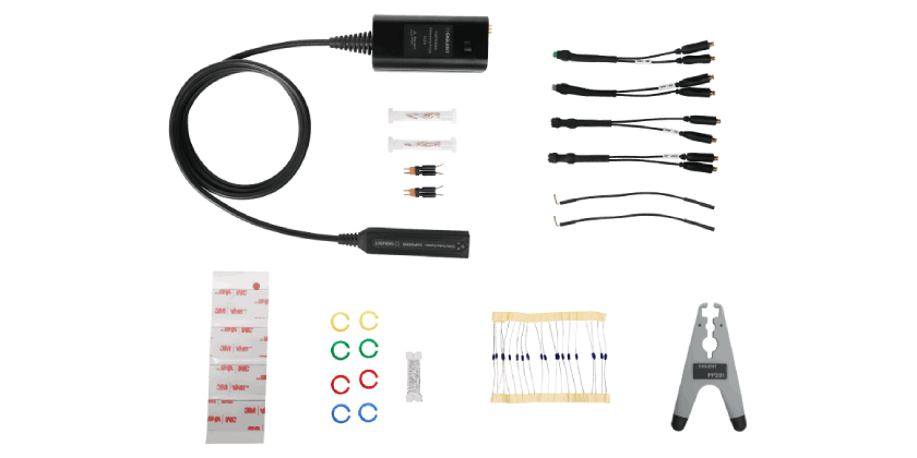
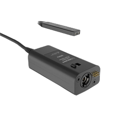
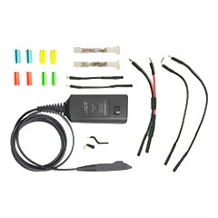
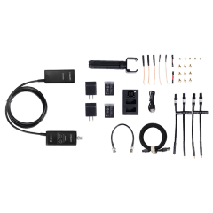
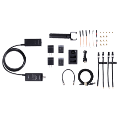
The SAP5000D is our highest performing active differential probe kit providing up to 5 GHz of bandwidth and low noise for detailed signal analysis. Its high input resistance and low input capacitance can ensure that the load introduced by the measurement system is minimized. SAP5000D active probe utilizes the SAPBus interface, making it suitable for oscilloscopes including the SDS5000X, SDS6000A and SDS7000A series. These probes do not need an additional external power supply and are automatically recognized by the oscilloscope.
9.Roll:
a)Supported Math and track cursors in Stop mode
b)Supported bandwidth limit
10.Webserver: supported inverted screenshot (according to the Image style setting in the Save menu)
11.Save/recall: File Manager: Supported to Select All; Supported to save all frames to a single file in Sequence mode
12.UI:Supported to specify Zoom region by drag a rectangle
13.Utility:Added English help; Supported password for screen saver
14. Fixed several bugs
a) When Log horizontal is used in FFT numbers are scrambled
b) Vertical axis of FFT optimized
c) Grid not aligned with numbers/wrong place with large offset
d)100BASE-T1 compliance test: displayed units of test result and judgment criteria are inconsistent
e) 100Base-TX and 1000Base-T: algorithm optimized
f) USB 2.0: compatible issue with USB IF recommended fixture
g) 1000BASE-T: transmission distortion test automatically executes without confirmation after completing one pair under the pairALL differential probe test
1. Supported new AP models: SDS7804AP, SDS7604AP
2. Supported Enhanced Bandwidth on 4GHz and below models (Only applied to units which are produced with 1.1.9.1R1 and later FW)
3. Improved the response speed in the case of deep waveform length
4. Compliance test:
a) Added MIPI-DPHY
b) Added 2.5G/5G/10GBASE-T
c) For USB2.0, added Receiver Sensitivity test, and supported upgrading the FW of the fixture by the scope
5.Math:
a) Added operators Tan, Atan
b) Added operator FFTPhase
c) Added new windows Black-Harris and Gaussian for FFT
6. Decode: added CANXL
7. Optimized refresh speed in the case of Roll + Zoom
8. Eye Diagram: added Second order PLL for Clock Recovery
9.Save/Recall:
a) Supported to save all segments in sequence mode to one
single .mat file
b) Supported to save all channels’ data to one file
c) Supported Full Screen view of pictures in File Manager
10. Supported Wake-on-LAN (Some setting change is necessary. Contact
SIGLENT for detailed information)
11. WGEN: supported the case in which built-in and external generators
are both in use 12. Fixed several bugs
1. Supported new model: SDS7604A H12
2. Cursor: new cursor strategy, supporting multi cursors
3. Made Option 16LA Standard
4. Fixed several bugs
a) Stuck at splash screen after upgrade
5. Power off operation at start-up process brings the instrument to dead
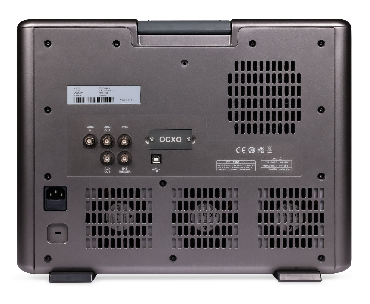
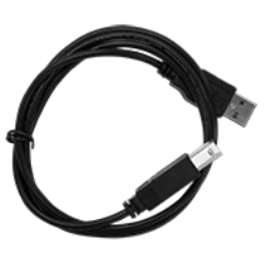
USB-A to USB-B. Used to connect instrument to PC for communication.
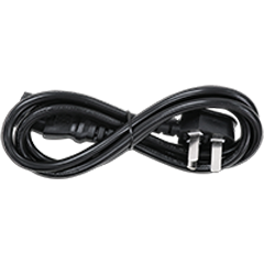
Power cord
The instrument comes standard with a power cord that conforms to the national standard of the user. Additional power cords in different regions can be purchased separately.
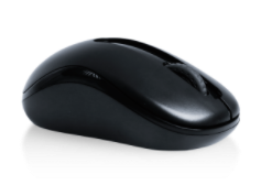
wireless mouse
A wireless mouse comes standard to help you improve your operating experience.
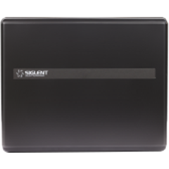
Protective Cover
Fasten on the front panel of the machine to protect the touch screen and knob to prevent the machine from being damaged by collision.
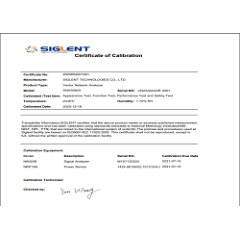
SDS7000A Calibration certificate
Calibration certificate
SDS7000A Quick Start
Quick guide
Probe
Product
Description
SP6150A
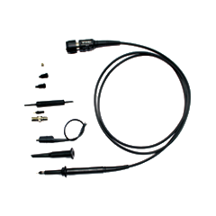
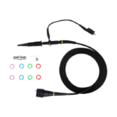
Passive probe, 1.5 GHz bandwidth, 10X attenuation ratio, input impedance of 1.8pF || 500Ω, with automatic identification function.
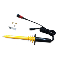
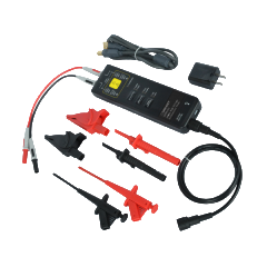
High voltage differential probe, bandwidth of 70 MHz, attenuation ratio of 50X/500X, maximum differential voltage of ±1500V, differential input impedance of 2pF || 10MΩ, BNC interface.
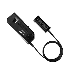
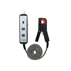
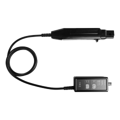
Current probe, DC-300 kHz bandwidth, attenuation ratio of 10X/100X, maximum input of 70Arms/200Ap-p, 9V adapter for power supply. Click to view the probe manual
CP6030
Current probe, DC-50 MHz bandwidth, 1X/10X attenuation ratio, maximum input of 30Arms/50Apk, jaw diameter of 5mm, powered by 12V adapter.
Optical isolation voltage probe, 500 MHz bandwidth, common mode rejection ratio of 160dB, measuring voltage of 2.5 V ~ 2,500 V, isolation voltage of ±60kV.
Optical isolation voltage probe, 1 GHz bandwidth, common mode rejection ratio of 160dB, measuring voltage of 2.5 V ~ 2,500 V, isolation voltage of ±60kV.
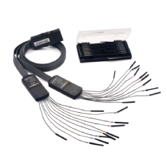
16-channel logic probe (hardware), sampling rate and storage depth are determined by oscilloscope, which is suitable for SIGLENT technology SDS7000A, SDS6000A, SDS6000L, SDS5000X HD, SDS5000X, SDS3000X HD, SDS2000X HD and SDS2000X Plus models.
Signals include various sine and square waves, AM, burst, and common serial bus signals.
DF2001A
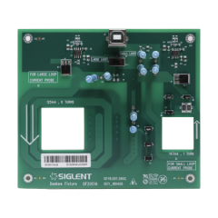
The phase calibration board, used in conjunction with power analysis software, is used to calibrate the phase difference generated by the voltage and current probes during transmission.
10M_OCXO_L
OCXO timebase (Assembled and calibrated in factory only)
When purchasing, determine whether installation is required.